How Is Commercial Beer Brewing Equipment Installed?
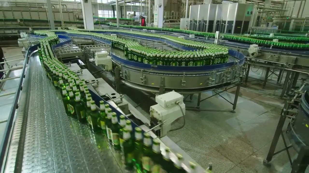
Commercial beer brewing equipment is installed by first confirming floor loading, ceiling clearance, drainage, electrical capacity, water supply, heating, glycol cooling, ventilation, and access routes. Large vessels are unloaded with suitable lifting equipment, positioned according to the approved layout, leveled, and anchored. Sanitary process piping, glycol lines, steam or heating connections, water, compressed air, gas, electrical wiring, sensors, and controls are then installed and tested. A commercial brewery commonly requires several specialist trades, and pressure vessels, electrical systems, gas services, and boilers may require local inspection. Before production, the brewery should complete leak checks, pressure checks where applicable, CIP cleaning, instrument verification, safety testing, and a water-only commissioning run.
The installation starts with the building rather than the tanks. A brewery should verify the equipment drawings against actual site dimensions, including door widths, ceiling height, structural columns, floor elevations, drains, and utility entry points. For a 20 BBL brewhouse, the footprint may be modest compared with the space required for fermenters, platforms, pumps, service access, and pipe racks. A simple measurement error of 2–3 inches can affect whether a tall vessel can be moved upright through a doorway.
That access requirement affects how equipment is delivered. Tall fermenters are often transported horizontally and then raised with cranes, gantries, or other approved rigging methods. The rigging plan should use the manufacturer's designated lifting points, account for the vessel center of gravity, and confirm floor and overhead capacity. Sanitary fittings, manways, glycol ports, and instrument connections should not be used as lifting points.
Once lifting has been planned, the floor and drainage system have to match the production process. Brewery floors routinely receive hot water, wort, beer, cleaning chemicals, and condensate. The FDA Food Code 2022 describes food-production surfaces as needing to be smooth, durable, and easily cleanable, with moisture-exposed areas using nonabsorbent surfaces; the exact local code for a brewery depends on its jurisdiction.
Drainage then determines several equipment positions. A tank placed directly over a drain may simplify cleaning, while a pump or heat exchanger placed too far from the process vessel can increase pipe length and cleaning volume. For a brewery with 8 fermenters, it is useful to check drainage around each vessel rather than assuming one floor drain will serve the entire room.
The next stage is equipment placement. The brewhouse is normally positioned with enough clearance for operators to reach valves, manways, sample ports, pumps, control panels, and platforms. Fermenters and brite tanks are then spaced for hose connections, glycol access, CIP work, pressure fittings, and routine service.
A practical layout review can use a simple clearance table:
| Area | Installation check |
|---|---|
| Tank top | Ceiling and lifting clearance |
| Tank sides | Valve, sensor, and service access |
| Tank base | Drain and outlet access |
| Pump area | Motor and seal replacement space |
| Heat exchanger | Plate removal clearance |
| Control panel | Electrical and operator access |
| Pipe runs | Drainability and support spacing |
That layout also sets the route for sanitary piping. Process lines may carry wort, beer, water, cleaning solution, or gas, so the pipe arrangement needs to match the intended cleaning and transfer sequence. Dead legs and unnecessary low points should be minimized, and horizontal sections should be installed with suitable drainage provisions.
For example, a 10 BBL brewhouse feeding 6 fermenters can require separate wort, beer, CIP, water, glycol, and gas connections. Each branch adds valves, fittings, gaskets, supports, and potential service points. Food-contact equipment should be designed and installed so that it can be effectively cleaned; FDA guidance also notes that equipment installation should facilitate cleaning of both the equipment and adjacent spaces.
The piping system then has to connect to the heat-transfer systems. Steam-heated brewhouses require steam supply, isolation, pressure-control equipment, condensate handling, and suitable insulation. Electric systems instead place much of the heating demand on the electrical service. A brewery drawing 150 kW of installed electrical load cannot be treated the same way as one drawing 30 kW, even if both produce similar beer volumes per batch.
Heating capacity is closely related to batch timing. A brewer may need to heat hundreds of gallons of liquor before mashing, bring the wort to boiling, and recover heat through a plate heat exchanger. When a brewery plans 4 batches per day, the heating system has far less idle time than a 1-batch-per-day operation, so the utility design needs to reflect the planned schedule rather than only the vessel nameplate size.
Cooling creates the next connection. Fermentation tanks normally use glycol jackets, with a chiller, reservoir, pump, supply header, return header, control valves, and temperature sensors forming the cooling loop. Suppose a brewery has 12 fermenters and each tank needs independent temperature control: the glycol distribution system then needs 12 controlled branches plus sufficient circulation capacity.
The glycol lines should be insulated continuously through the production area. A gap of only 1–2 meters in insulation can cause condensation on a cold pipe, especially in humid rooms. After piping is completed, installers should flush the circuit, remove trapped air, confirm flow through each branch, verify the glycol concentration specified by the chiller manufacturer, and test the tank temperature response.
Temperature control then depends on instrumentation. Each fermenter may have a temperature probe connected to a controller that opens a glycol valve when the tank rises above its setpoint. During commissioning, the displayed temperature should be compared with an independent calibrated reference. For a sample of 10 tanks, recording readings from all 10 at the same test point makes it easier to spot a single miswired or poorly calibrated sensor.
Electrical work follows the equipment schedule. Pumps, agitators, heating systems, refrigeration compressors, controls, lighting, packaging machines, air compressors, and auxiliary systems all contribute to the building's electrical requirement. Motor voltage, phase, current rating, grounding, overload protection, and rotation should be checked before normal operation.
The control system then ties the electrical and mechanical equipment together. A programmed sequence may open a valve, start a pump, monitor a level signal, and stop the pump when the vessel reaches a set condition. During commissioning, each input and output should be tested individually. If a system has 24 automated valves, checking all 24 rather than sampling only 5 can prevent a single wrong connection from remaining unnoticed.
Gas and ventilation require their own installation review. Carbon dioxide is used for purging, tank pressure, and beer handling, while nitrogen may be used for selected packaging or dispensing applications. Gas piping requires compatible regulators, valves, fittings, and pressure controls, while rooms with potential CO₂ accumulation need ventilation and applicable monitoring provisions.
The pressure side also requires documented testing. ASME's Boiler and Pressure Vessel Code has been used for boiler and pressure-vessel design, construction, inspection, and testing since 1915, although the exact regulatory requirements for brewery vessels depend on the vessel design and jurisdiction. A tank operating at pressure should therefore be checked against its manufacturer's documentation and the local authority requirements before it is placed into service.
Cleaning equipment is installed alongside the process system rather than added later. A CIP setup may include a caustic tank, acid tank, rinse-water source, pump, spray device, return line, valves, and heating provision. The pipe routing should allow the intended cleaning solution to circulate through tanks, pumps, valves, hoses, and heat exchangers at the required flow and temperature.
Sanitary finish matters during this stage. FDA guidance describes food-contact surfaces as corrosion-resistant, durable, easily cleanable, relatively nonabsorbent, smooth, and free of open seams; particular construction requirements depend on the applicable facility rules. In a new brewery, welds, fittings, and equipment interiors should therefore be inspected before the first beer batch rather than after production has already started.
The complete installation can then be checked as a connected system. A useful commissioning sequence is:
-
Flush water lines and inspect drains.
-
Test pumps and verify motor rotation.
-
Test glycol circulation on every connected tank.
-
Check heating, steam, or electrical heating functions.
-
Verify temperature, level, pressure, and flow instruments.
-
Test automated valves and interlocks.
-
Run the CIP circuit with water.
-
Inspect every accessible connection for leaks.
Running water before wort provides a lower-cost way to check transfer paths, pumps, valves, heating, cooling, drain behavior, and control sequences. A brewery completing a 1,000-gallon water trial can measure actual transfer time, pump behavior, heat-exchanger performance, drain rate, and tank temperature response without consuming raw materials.
The results from that trial should then be compared with the design documents. If a wort transfer was designed for 20 gallons per minute but the installed system delivers only 12 gallons per minute, the difference may come from undersized piping, excessive fittings, valve selection, pump configuration, or elevation. Recording measured values from at least 3 repeated water runs can help separate a stable system characteristic from a one-time installation issue.
That check leads into final cleaning and production release. Stainless-steel vessels and piping may contain fabrication residue, dust, oil, or installation debris, so the brewery should follow the equipment supplier's cleaning and passivation instructions before product contact. Cleaning chemicals should be used at the concentration, temperature, pressure, and contact time specified by the chemical supplier and equipment instructions.
For a commercial system, documentation should be completed at the same time. The brewery should retain equipment drawings, valve lists, electrical schematics, vessel certificates where applicable, instrument settings, pump data, utility specifications, and commissioning records. A 2024 FDA update to the 2022 Food Code shows that equipment sanitation and facility requirements continue to be refined, so project records should identify the actual jurisdiction and code edition used for approval.
A brewery can then use the completed installation records for future expansion. If the first phase has 6 fermenters and the owner expects to add another 6, spare electrical capacity, additional glycol branches, drain locations, pipe-rack space, and utility headers can be considered during the original installation. The same planning approach applies to a new hgmc brew system where vessel count, heating method, cooling demand, automation level, and available building services need to be matched before equipment is permanently installed.
The final production setup should leave every major vessel accessible, every required utility connected, every control point identified, and every cleaning route documented. A 12-tank brewery, for example, should have clear records showing which glycol valve, temperature sensor, CIP branch, and process line belongs to each vessel before routine production begins.